CALIFORNIA STATE UNIVERSITY, FULLERTON
Computer Engineering

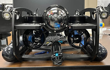
2022 AUV
Vehicle Components
-
2 custom batteries
-
2 custom battery cases
-
BlueRobotics frame
-
BlueRobotics 4” chassis
-
BlueRobotics gripper
-
6 BlueRobotics thrusters
-
2 BlueRobotics LEDs
-
BlueRobotics camera
-
Power distributor
-
Speed controllers
-
Electronics tray
-
Raspberry Pi
-
Intel Neural Compute Stick 2

Block Diagram
The power supply consists of the two batteries that were designed specifically for the AUV. This power supply goes through a power distributor to power the six thrusters, and the power supply also powers the two LEDs as well as the gripper. The Raspberry Pi will be used to control the six thrusters, two LEDs, and gripper; there is also a display connected to the Raspberry Pi. The camera will be used as an input and will be used mainly for machine learning and the autonomous side of the AUV.
.jpg)
Complete Schematic Diagram
The diagram below shows how all of the individual components are connected to each other and specifically to the Raspberry Pi.

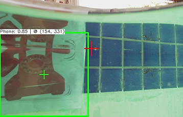
Object Detection/Navigation
-
Computer Vision
-
Machine learning training done for YOLOv4-tiny model
-
Camera detects objects and maneuvers accordingly
-
AI model uploaded to Raspberry Pi
-
Trained to complete tasks
Modifications
-
Some issues encountered by the team were thermal issues due to the battery discharging a lot of heat that we designed a system so that the batteries are not in the same compartment as the Raspberry Pi and other internals.
-
We also had to figure out how to make the battery case waterproof, which we solved by 3-D printing a custom designed battery case, covering it with layers of epoxy, and sealing with waterproof sealant.
-
Another issue was that we originally had code to test the components on an Arduino yet we had a Raspberry Pi in our design. In order to fix this, we ported our code from the Arduino to the Raspberry Pi.
-
And, initially, we planned to only have one battery. However, with the number of components that needed power and with the amount of power these components needed, we simply did not have enough power. Thus, we had to change the design to include two batteries.
-
Also, the previous team originally had a 8” chassis. We modified the design to use a 4” chassis.
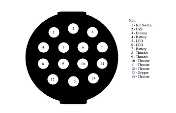
End Cap Diagram
The diagram below shows how the components are connected through the end cap of the chassis.